Most of the electrcial and electronics projects include controlling part i.e. brain, which is a microcontroller. If we talk about microcontroller 8051, then you need to program it time and again for testing purposes and then integretaing the microcontroller 8051 with the ciruit.
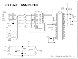
So we want to fuse a programming facility in our programming tool with your programmed code i.e microcontroller 8051. Now the programmer we are going to design, supports the devices in the 8031 family of Atmel, AT89SXX, and its AVR microcontroller AT90SXXXX series controllers. Here is the circuit diagram of a standalone spi programmer.
Here interfacing of the power is provided by PC USb port as it is very easy to provide the power using the system you are using for programming purposes. A USB port can supply a max of 100mA current. You have to get a cheap USB cable, cut the cable at one end and attatch the two power lines i.e. black indicates ground and red indicates 5V.
PC parallel port is used to provide the parallel lines to the microcontroller. To isolate the programming device , microcontroller 8051 and PC parallel port we use 74HCT541 ic. This acts as buffer for the parallel port signals. It is necessary to ensure that the programmer works with typical 3V type parallel port. A 40-pin zip socket is used for 8051 microcontroller.
In the diagram below DB25 connector shown denotes the PC parallel port. BE, CK, D0 and RS are the output lines of parallel port while DI is the input line. Sip resisstors are used to pull the lines high. I would recommend to use the resistors for all the output lines on the kit as well to provide ease in testing purposes.
circuit diagram
software
The ISP-30a.zip files consisits of the main programm and the driver used for i/0. Copy all the files in the same folder. For the auto hardware deection it is necessary to short pin2 and 12 of DB 25 connector otherwise software uses the default parallel port i.e. LPT1
You can download the software here
ISP-30a
So we want to fuse a programming facility in our programming tool with your programmed code i.e microcontroller 8051. Now the programmer we are going to design, supports the devices in the 8031 family of Atmel, AT89SXX, and its AVR microcontroller AT90SXXXX series controllers. Here is the circuit diagram of a standalone spi programmer.
Here interfacing of the power is provided by PC USb port as it is very easy to provide the power using the system you are using for programming purposes. A USB port can supply a max of 100mA current. You have to get a cheap USB cable, cut the cable at one end and attatch the two power lines i.e. black indicates ground and red indicates 5V.
PC parallel port is used to provide the parallel lines to the microcontroller. To isolate the programming device , microcontroller 8051 and PC parallel port we use 74HCT541 ic. This acts as buffer for the parallel port signals. It is necessary to ensure that the programmer works with typical 3V type parallel port. A 40-pin zip socket is used for 8051 microcontroller.
In the diagram below DB25 connector shown denotes the PC parallel port. BE, CK, D0 and RS are the output lines of parallel port while DI is the input line. Sip resisstors are used to pull the lines high. I would recommend to use the resistors for all the output lines on the kit as well to provide ease in testing purposes.
circuit diagram
The ISP-30a.zip files consisits of the main programm and the driver used for i/0. Copy all the files in the same folder. For the auto hardware deection it is necessary to short pin2 and 12 of DB 25 connector otherwise software uses the default parallel port i.e. LPT1
You can download the software here
ISP-30a

No doubt the most basic requirement of 8051 MCU. Thumbs up
ReplyDelete8051 Programming
This is also a very good post which I really enjoyed reading. It is not every day that I have the possibility to see something like this.. Concrete balcony crack repair
ReplyDelete