Thursday, 2 June 2011

Universal Triac Control with Optocoupler

This universal triac controller circuit with optocoupler solves the problem that triacs have when functioning at low temperatures (triac needs higher gate current) by adding a transistor at the output of the optocoupler circuit.
The transistor amplifiers the trigger pulse coming from the optocoupler and the gate current is high enough to trigger the triac in all temperature cases.
How does the circuits works?
The base of the transistor is driven by the OC. C2 works as capacitive bias resistance to avoid power losses and it also helps avoid DC loading of the supply line. The switch current is limited by R3. D1 works as one-way rectifier while C1 works as ripple filter.
D2 stabilize the rectified voltage to 15 V.
T1 conducts when the OC sends a pulse to its base. C discharges through the collector-emitter line. The trigger current is limited by R2 to around 40 mA.
The discharge current time of C1 is less than 1 ms.
The RC circuit R4 and C3 protects the triac from voltage spikes.
This is very important in all inductive loads.
 

Electronic Lie Detector Circuit

This electronic lie detector circuit will give two readings: one for difficult questions for the subject and another to show its emotional state in general.
The emotional states are detected not only by heart beat accelaration and trembling hands but also an increase in skin humidity whose resistance decreases causing the entry into operation of the lie detector.

Two electrodes can be used as a flexible wire, bare, wrapped around fingers or wrist.
In order to not influence the measurement result the device must be powered from two 9 Volts batteries.
Each change in resistance, and therefore the voltage at the input circuit will be amplified by operational amplifier A1, which also serves as separator. The output signal will determine, by R3, a deviation of the measuring instrument.
General emotional state of a person can be assessed by measuring the average resistance of the skin over a period of time. The indication is provided by an indicator instrument connected to point B of the circuit. Operational amplifier A2 is connected as an integrator and allows the circuit to automatically adjust according to the average resistance of the skin.
Length of time to measure the skin resistance is determined by R5, C2 and C3. Until such time elapses, the lie detector gives no indication although diodes D1 and D3 provide a rapid response of the circuit.

Potentiometer P1 allows you to adjust the time delay of the circuit. Since skin resistance varies from one person to another, may be necessary to change the resistance value R1. This resistance can be replaced with a potentiometer.
Reading a great value to the instrument connected to the output of B indicates that subject’s skin resistance is low (which is a characteristic of people with sticky hands) and it is advisable to reduce the value of R1.
lie detector components list
R1 = 47K
R2 = 1M
R3 = 3.3K
R4 = 10K
R5 = 10M
P1 = 10K
C1 = 100n
C2 = C3 = 470n
D1 = D2 = 1N4148
IC1 = IC2 = LF356

Monday, 30 May 2011

Ultrasonic transmitter 40kHZ for your Robot

40kHZ ultrasonic transmitter circuit (1)
40kHZ one ultrasonic transmitter circuit, the F1 ~ F3 three oscillators in the F3 is 40kHZ square wave output, frequency mainly by C1, R1 and RP decided to adjust the adjustable resistance with a frequency of RP. F3 transducer excitation output T40-16 at one end and the inverter F4, F4 transducer excitation output T40-16 the other end, therefore, join F4 doubling the excitation voltage. Capacitors C3, C2 and F4 F3 balance the output of the waveform is stable. Inverter circuit, F1 ~ F4 with the CC4069 in four of six inverter inverter, and the remaining two do not (input should be grounded.) Power Supply 9V laminated battery. F3 output frequency measurement should be 40kHZ ± 2kHZ, or should be adjusted RP. Transmitting ultrasonic signals greater than 8m.
40kHZ ultrasonic transmitter circuit (2)  
  40kHZ second ultrasonic transmitting circuit, the circuit transistors VT1, VT2 form strong feedback resonator oscillator, the oscillation frequency equal to the ultrasonic transducer T40-16 resonant frequency. T40-16 is the feedback coupling element, the circuit is the output for the transducer. T40-16 is similar at both ends of the square wave oscillation waveform, voltage amplitude close to the power supply voltage. S is the power switch, click S, T40-16 can drive a string of 40kHZ emitted ultrasonic signals. Circuit voltage of 9V, the operating current of about 25mA. Transmitting ultrasonic signals greater than 8m. Circuit can work without debugging.
40kHZ ultrasonic transmitter circuit (3)  
   40kHZ ultrasonic transmitter circuit, produced by the VT1, VT2 positive feedback form feedback oscillator. Circuit oscillation frequency depends on the feedback element of the T40-16, the resonant frequency of 40kHZ ± 2kHZ. Frequency stability, no need to make any adjustment by the T40-16 as a transducer of the ultrasonic signals emitted 40kHZ. Inductor L1 and capacitor C2 for resonance tuning role played in the 40kHZ. Voltage of the circuit to adapt to a wide (3 ~ 12V), and the frequency change. Using fixed inductors, inductance 5.1mH. Machine operating current of about 25mA. Transmitting ultrasonic signals greater than 8m.
40kHZ ultrasonic transmitter circuit (4)  
   40kHZ four ultrasonic transmitter circuit, which consists of four complete and non-oscillation, and gate drive functions CC4011 by ultrasonic transducer T40-16 to control the receiver, the ultrasound radiation. Which formed the door YF1 controlled oscillator with the door YF2, when S is pressed, the oscillator start-up, adjust the RP change the oscillation frequency, should be 40kHZ.Oscillations are controlled by YF4, YF3 drive differential phase composition of the work, when YF3 output goes high, YF4 certain output low; YF3 output low, YF4 output high. The T40-16 level control issue 40kHZ ultrasonic transducer. Circuit YF1 ~ YF4 four high-speed CMOS circuit 74HC00 NAND gate circuit, the output drive current is characterized by large (greater than 15mA), high efficiency. Circuit voltage of 9V, operating current greater than 35mA, transmitting ultrasonic signal is greater than 10m.
40kHZ ultrasonic transmitting circuit (5)  
  40kHZ five ultrasonic transmitting circuit, time base circuit by the LM555 and the external components, the 40kHZ multivibrator circuit, adjust the resistance of resistor RP can change the oscillation frequency. 3 feet from the LM555 output drives ultrasonic transducer T40 -16, so that emit ultrasonic signals. Circuit is simple and easy system. Circuit voltage of 9V, working current 40 ~ 50mA. Transmitting ultrasonic signals greater than 8m. LM555 NE555 direct replacement is available, the effect is the same.

Thursday, 26 May 2011

Ultrasonic reciever for your Robot

Hi friends!
    Here is a common problem for all the electrical engineering students who have interest in the field of robotics and are pretty much into it. You always want to know where the hurdles or obstacles are located in the path of the robot so that it may not be collided with it or you may get some observations about the location of the walls etc.
    Here is a simple electronic project which describes the ultrasonic receiver circuit and its working. get a pair of ultrasonic transducers from market. these are pretty cheap and easily available. And get 2 Op amps 741.  Circuit is very easy to understand as shown in the diagram. Initial stage couples the received signal from the receiver to op amp input. We assume here that the ultrasonic receiver receives a signal of 40 kHz reflected from an obstacle in the path of the robot. And this signal was generated from an ultrasonic transmitter of 40 KHZ. Now the first op-amp stage amplifies the received signal an the second stage compares the receive signal with a particular signal level. You can adjust this level by changing resistors values for the desired signal level. This reflects the distance of obstacle from which the ultrasonic wave is reflected. By attaching several comparators set at different signal levels you can find different range calculations.


Friday, 20 May 2011

Quiz project using IC 555

This project can be used to understand and develop an application of ic 555 timer. The project can be used for a quiz with up to 5 contestants (or teams). Each of the contestant have a trigger push-switch in his/her hand. And an LED is fitted on the table. When a trigger switch is pressed the corresponding LED lights , sounds the bleeper and it keeps other trigger switches away from triggering or working. So this shows which contestant was the first to press the switch. A reset push switch which is operated by quiz master, is used to cancel the bleeper and switches of the LED so that the next question may b asked and the switches can be operated again.
See the circuit diagram. It consists of four ic 555 timer operated in bistable mode( stable in both high and low outputs) which are triggered or reset when their inputs are low. The reset input of all the ic 555 is joined together and operated by a single reset push-switch. The trigger switches are connected to the bistable trigger( pin2) through a 0.1 uF capacitor so that only the initial press triggers the bistable; and continying to hold the switch closed will have no effect. Now the switch is directly connected to the bistables. This prevents the quizmaster from resetting the circcuit until the trigger swicth was released. As it has been observed that some contestants hold the switch until they are asked to give their answer.  When a trigger switch triggers a bistable output (pin 3) lights an LED and makes the trigger line 'high', this prevents any other bistable being triggered and sounds the bleeper. We have used a diode to link the output to the trigger line.

Monday, 16 May 2011

Microcontroller 8051 based Visitor Counter

This is one of the basic and easily implementable circuit for the basic knowledge and practice of an electrical engineer and engineering student using microcontroller 8051. Visitor counter can be used on numerous places where the data for the persons at a perticular place need to be kept such as banks, private places etc.
    Here i have designed a basic circuit using 555 timers. And basic infrared reciever TSOP1736 are used as sensors for the detection of the persons entering and leaving. There are two sensors placed at some distance so that when a person enters the room, the sensor output cuts when the person passes in front of one of them. so when a person leaves, the order in which sensors give low pulse reverses.
            555 is used in monostable operaton as can be seen from the diagram. In monostable operation, 555 gives output only when input trigger pulse goes down. This happens when a person passes in front of the sensor.
Both outputs from the sensors are fed to the microcontroller 8051. Microcontroller checks in which order the sensors are illuminated. And gives output to the 7 segments accroding to the programm. This one is very easy to practice and get some experience of microcontroller 8051 programming.

Saturday, 14 May 2011

Microcontroller 8051 programmer kit

Most of the electrcial and electronics projects include controlling part i.e. brain, which is a microcontroller. If we talk about microcontroller 8051, then you need to program it time and again for testing purposes and then integretaing the microcontroller 8051 with the ciruit.
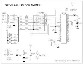
            So we want to fuse a programming facility in our programming tool with your programmed code i.e microcontroller 8051. Now the programmer we are going to design, supports the devices in the 8031 family of Atmel, AT89SXX, and its AVR microcontroller AT90SXXXX series controllers. Here is the circuit diagram of a standalone spi programmer.
                    Here interfacing of the power is provided by PC USb port as it is very easy to provide the power using the system you are using for programming purposes. A USB port can supply a max of 100mA current. You have to get a cheap USB cable, cut the cable at one end and attatch the two power lines i.e. black indicates ground and red indicates 5V.
                PC parallel port is used to provide the parallel lines to the microcontroller. To isolate the programming device , microcontroller 8051 and PC parallel port we use 74HCT541 ic. This acts as buffer for the parallel port signals. It is necessary to ensure that the programmer works with typical 3V type parallel port. A 40-pin zip socket is used for 8051 microcontroller.
                In the diagram below DB25 connector shown denotes the PC parallel port. BE, CK, D0 and RS are the output lines of parallel port while DI is the input line. Sip resisstors are used to pull the lines high. I would recommend to use the resistors for all the output lines on the kit as well to provide ease in testing purposes.

circuit diagram
 
software

The ISP-30a.zip files consisits of the main programm and the driver used for i/0. Copy all the files in the same folder. For the auto hardware deection it is necessary to short pin2 and 12 of DB 25 connector otherwise software uses the default parallel port i.e. LPT1
You can download the software here
ISP-30a