
40kHZ ultrasonic transmitter circuit (1)
40kHZ one ultrasonic transmitter circuit, the F1 ~ F3 three oscillators in the F3 is 40kHZ square wave output, frequency mainly by C1, R1 and RP decided to adjust the adjustable resistance with a frequency of RP. F3 transducer excitation output T40-16 at one end and the inverter F4, F4 transducer excitation output T40-16 the other end, therefore, join F4 doubling the excitation voltage. Capacitors C3, C2 and F4 F3 balance the output of the waveform is stable. Inverter circuit, F1 ~ F4 with the CC4069 in four of six inverter inverter, and the remaining two do not (input should be grounded.) Power Supply 9V laminated battery. F3 output frequency measurement should be 40kHZ ± 2kHZ, or should be adjusted RP. Transmitting ultrasonic signals greater than 8m.

40kHZ ultrasonic transmitter circuit (2)
40kHZ second ultrasonic transmitting circuit, the circuit transistors VT1, VT2 form strong feedback resonator oscillator, the oscillation frequency equal to the ultrasonic transducer T40-16 resonant frequency. T40-16 is the feedback coupling element, the circuit is the output for the transducer. T40-16 is similar at both ends of the square wave oscillation waveform, voltage amplitude close to the power supply voltage. S is the power switch, click S, T40-16 can drive a string of 40kHZ emitted ultrasonic signals. Circuit voltage of 9V, the operating current of about 25mA. Transmitting ultrasonic signals greater than 8m. Circuit can work without debugging.
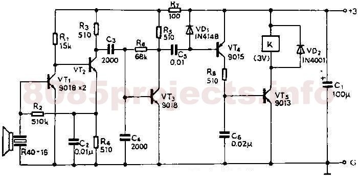
40kHZ ultrasonic transmitter circuit (3)
40kHZ ultrasonic transmitter circuit, produced by the VT1, VT2 positive feedback form feedback oscillator. Circuit oscillation frequency depends on the feedback element of the T40-16, the resonant frequency of 40kHZ ± 2kHZ. Frequency stability, no need to make any adjustment by the T40-16 as a transducer of the ultrasonic signals emitted 40kHZ. Inductor L1 and capacitor C2 for resonance tuning role played in the 40kHZ. Voltage of the circuit to adapt to a wide (3 ~ 12V), and the frequency change. Using fixed inductors, inductance 5.1mH. Machine operating current of about 25mA. Transmitting ultrasonic signals greater than 8m.

40kHZ ultrasonic transmitter circuit (4)
40kHZ four ultrasonic transmitter circuit, which consists of four complete and non-oscillation, and gate drive functions CC4011 by ultrasonic transducer T40-16 to control the receiver, the ultrasound radiation. Which formed the door YF1 controlled oscillator with the door YF2, when S is pressed, the oscillator start-up, adjust the RP change the oscillation frequency, should be 40kHZ.Oscillations are controlled by YF4, YF3 drive differential phase composition of the work, when YF3 output goes high, YF4 certain output low; YF3 output low, YF4 output high. The T40-16 level control issue 40kHZ ultrasonic transducer. Circuit YF1 ~ YF4 four high-speed CMOS circuit 74HC00 NAND gate circuit, the output drive current is characterized by large (greater than 15mA), high efficiency. Circuit voltage of 9V, operating current greater than 35mA, transmitting ultrasonic signal is greater than 10m.

40kHZ ultrasonic transmitting circuit (5)
40kHZ five ultrasonic transmitting circuit, time base circuit by the LM555 and the external components, the 40kHZ multivibrator circuit, adjust the resistance of resistor RP can change the oscillation frequency. 3 feet from the LM555 output drives ultrasonic transducer T40 -16, so that emit ultrasonic signals. Circuit is simple and easy system. Circuit voltage of 9V, working current 40 ~ 50mA. Transmitting ultrasonic signals greater than 8m. LM555 NE555 direct replacement is available, the effect is the same.

No comments:
Post a Comment